I’ve been collecting information on Maynooth for a long time. This rough layout plan is based on many photographs of the site, as well as Keith Hansen’s track arrangement drawing in his book “Last Trains From Lindsay”, published 1997. With some modification to fit available space, this is my plan for the model.
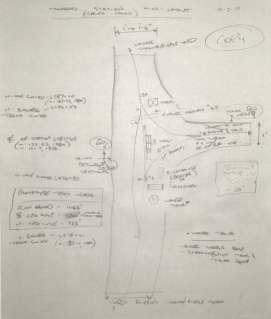
Site plan for Maynooth. The site remained essentially unchanged from circa 1910 to when the rails were taken up circa 1983. Mileage and chainage references are from where the train order board was at Trenton, and after about 1965 from Picton. Note that this tentative plan is annotated with modelling notes for an HO scale layout. I changed the location of the break at the joint of baseboard sections to better suit the requirements of travel. Every structure that I plan to model on this layout is shown here.
Having determined what elements I want to incorporate in my rendering of Maynooth, I set out to draw a full-scale track plan. I have never been that good at planning a layout to scale in miniature, and I follow prototype practice where I can. This rules out the use of many CAD track design programmes such as Templot. Pencil and paper wins the day with me, because I can plan very accurately how track is to be placed. When I build, it fits the first time.
Maynooth station was to the outside of a gentle curve, with a wye completing the surround of its concrete station. In front of the station across from the main track was the business track. This comprised the entirety of Maynooth’s “yard” referenced in the Employee Timetables.
The first step was to get a sheet of large white “banquet paper” to draw the full size track plan on. Supplied in a 36-inch-wide roll, I have used this paper for drawing out full-size trackplans before. I cut off a seven-foot length of this paper and went to work. The desired length of the main track section is about 6 feet 6 inches (two metres) long, by a foot (30 centimetres) wide. This allows it to fit in my compact SUV for travel. The two legs of the wye will be built on a separate frame and were drawn up on the actual roadbed afterward, where it was easier for me to plan these tracks out in situ. I am still deciding how to model track leading to staging yards, or whether to use perhaps 3 foot or metre long singe track that’ll attach to either end of the main track to create a place for trains to run “from” and “to”.
As you can see from the above rough site plan, much of the track is curved. I used a method for laying out curves of various radii that has stood me in good stead for decades. NMRA Data Sheet D3b.3 gives a number of different ways to lay out model easement curves. I prefer the tangent method shown on Page 4 of this Data Sheet.
With a basic calculator, it’s easy to calculate minimum radii BEFORE a single tie or rail is laid. This is important as I handlay rails onto wood and PC board ties. It’s much more difficult to lift and re-lay track built using this method than when using ready-made commercial turnouts and flextrack.

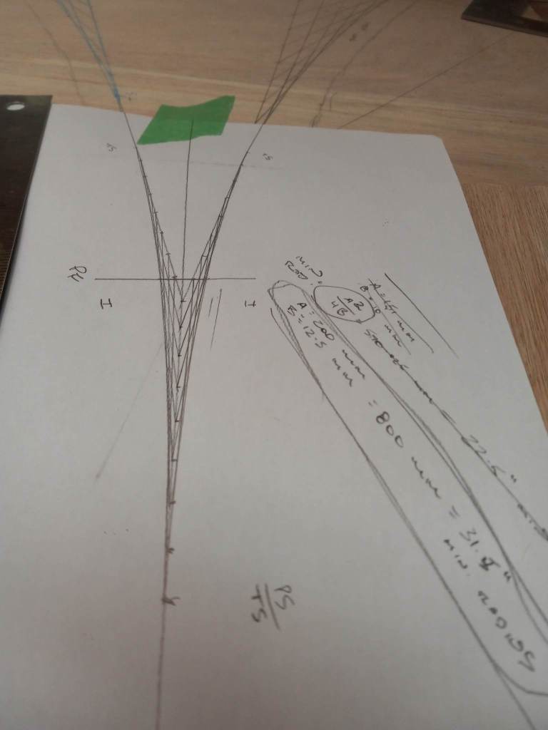
Laying out curves using the tangent method described in this article. Two intersecting tangents are connected, then lines drawn from various locations or stations on each tangent to the other tangent. The NMRA Data Sheet referenced above will explain this process better than I can with my feeble prose.
The main track in front of the station is on a gentle curve of calculated 96″ minimum radius. This is a model approximation of that curve. Tangents are run off this curve either end of it, on which turnouts to the wye and business tracks are located, all NMRA number 6. Other curves are sharper. The business or loop track across the main track from the station was laid out so that an at least scale 20 foot spacing from the main track occurred for some of its length, to comply with Railway requirements for use of track switches by train crew, and allow non-railway employees working in cars spotted on the business track the room to work as far as possible away from passing trains. I’ve used easement curves calculated to produce a minimum radius of 48 inches on curves in this track. This allows me to couple cars spotted in this track even using Kadee #58/153/158 “scale head” couplers without hopefully touching the couplers during switching moves other than with a sharpened skewer described in my post from earlier this year, “Getting the Snip”.

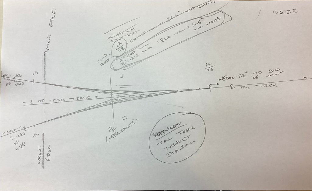
Showing detail of north end of main track, with turnout to business track off main track in centre of photo. “PS” is the tip of the switchpoints; “PF” is the very tip of the point of the frog. “ICL” is the location of the intersection of track centrelines of the main and diverging tracks. Where the lines diverge by your track gauge will always be the point of the frog. This is referred to as the “theoretical point of the frog” on prototype turnout diagrams, but for modelling purposes, is good enough for us to locate our frog point. In the upper part of the photo is the centre line of the north wye track branching off the main. This is laid out using the tangent method, as all curves are.
The north leg of the wye was drawn, running a tangent from the diverging route of the number 6 turnout connecting it to the main track at the left of the photo. I drew another tangent almost at a right angle to the main track, joining the two tangents. This second tangent is the centreline of the wye’s tail track. I was able to calculate that the minimum radius of a curve connecting the two tangents would be 25 inches. In HO scale, this will accommodate just about anything that I envision running over Code 55 rail, from diesel switching locomotives to Ten Wheeler steam locos and ever rebuilt GP9R’s such as CN’s 4000/4100/7000/7200 series locos. This corresponds to the largest loco’s that CN would have run on this track; and the GP9’s would have maybe been prohibited from traversing this part of the Maynooth/Marmora Sub anyway.
The south leg of the wye is an interesting challenge to locate; the prototype turnout had two curved legs. The main track is one curved leg and is of varying radius as it passes through a transition curve. The diverging route to the south leg of the wye is part of a transition curve, starting from a tangent drawn off the main track curve. This calls for its own explanation which I will offer to those interested; I understand that if you’ve read this far, I probably will bore you if I’ve not already. I used the same data from the north leg of the wye and angle between two tangents to produce another 25-inch minimum radius transition curve, this time on the south leg of the wye.
Centreline diagram for turnout where north and south wye legs meet. I ran tangents off the north and south wye tracks. In the top of the photo are the end of the transition curves forming the wye legs. I ran tangents off those curves and joined them. Then drew transition curves from the tangent off the wye to my desired tail track centreline.
The connection between the two legs of the wye at the tail/pull-back/headshunt for the wye befuddled me for a few days. I decided to run tangents off the wye legs near the end of their transition curves. These produced what normally would be a turnout so sharp a radius that it’d be useable by four-wheel industrial loco’s and streetcars, but not much else. I got out a sheet of legal size paper and a pencil. What I designed is shown above. By running the two wye track tangents together, I was able to create two transition curves of 31.5″ minimum radius, touching a few inches away from the frog. The turnout may look a bit toylike, yet it’s a proper wye turnout. A peculiarity of a wye turnout is that is effectively twice the turnout number of a straight turnout if laid with one leg straight, because both routes diverge through the turnout. This is the only non-standard turnout that I will use. It was either this, or play with track geometry until I could use a standard turnout like a #5 or #6. As I build my own track, a non-standard turnout is not an issue for me to use or build. Its use also gives me a tail track of about two feet long, enough track length to turn a Ten-Wheeler and combination car or caboose in one move. Were I to use a standard turnout here, my tail track might only be half as long unless I built even longer benchwork for the wye, which I do not want.
The end result is a track design that I was happy with and will accommodate my choice of rolling stock for this layout. Now to transfer it to benchwork and roadbed.

Maynooth is a location that I’ve wanted to model for three or more decades. It was a minor branchline terminal on CN, but this location was intended by Cleveland Ohio industrialist Charles Ritchie to be an intermediate terminal on his Central Ontario Railway on its route to Sudbury Ontario. Ritchie died the year after this terminal and station were built in 1907, and the line only got another fifteen or so miles north to Wallace, near the south end of Algonquin Park. About 1910, the railway was taken over by Mackenzie and Mann’s Canadian Northern Railway (CNoR). A CNoR 1918 employee timetable for the line shows mixed and passenger trains running alternate days of the week from Trenton except Sunday, with train crews staying overnight at Maynooth. 1919 saw the CNoR taken into the fledgling Canadian National Railways, where this line was one of many in the area. With the plethora of rail lines owned by CN in the area, this terminal appears to never have progressed beyond a wye and a runaround track, which stayed in place until the rails were lifted circa 1983. The photo shows a boxcar on that runaround track, with the south leg of the wye just visible to the right of the station.
Mixed passenger/freight train service ran here into the 1950’s out of Bancroft. With the loss of passengers to automobiles and the paving of Highway 62 in the early 1950’s, the line between York River and Maynooth became freight-only. By the mid 1950’s, the line between Bancroft and Wallace was served by a Lindsay crew and their diesel loco (either a Montreal Locomotive Works RSC-13 or a General Motors Diesel SW1200RS) travelling over the Irondale Sub twice a week, running up to Maynooth and Wallace from Bancroft on the day between runs to and from Lindsay. Lumbering and gravel extraction sustained this line into the 1970’s. Raw wood railway ties were collected from sawmills north of Maynooth for creosote preservative treatment down the line in Trenton, and a gravel pit a few miles north of Maynooth contributed traffic as well. Highway 62 nearby took most of that traffic away by the 1970’s, and the lumber stands were logged out by then.
With the disappearance of traffic on this line, CN filed for abandonment in 1979. Hearings took place in 1980, and the rails were taken up a few years later. The concrete station building remains as a reminder of what was. There was a local movement to preserve and possibly restore it, but little has come of this so far. Surrounded by a chain-link fence, the station slowly deteriorates. The concrete walls can last for years yet, but the roof is collapsing, allowing water to get at the walls. The resulting freeze/thaw cycles in much of the year cannot be good for that concrete. Who knows how long the building will stand?
The bucolic setting of the Maynooth station site appealed to me ever since I read of and saw photos of it in James Plomer’s book “Desperate Venture”, a history of the Central Ontario Railway. I like it for its almost forlorn location; there is little settlement here to this day other than the former McAlpine hotel north of the station which survives as a bed and breakfast establishment. The village of Maynooth is a mile or so west of the station on a hilltop. This location not having changed much between 1907 and 1983 allows me to run locomotives and cars suitable for many eras without changing the structures or track arrangements. I can even run other railways’ rolling stock, like that from my proto-freelanced Midland Railway of Canada. Central Ontario Railway 4-4-0 steam locomotives or CN rebuilt diesel-electric GP9’s? Both are appropriate on this as a model layout. This offers a lot of modelling flexibility.
And the opportunity to bring back a little bit of history in model form is enticing in its own right.
How I designed this location into a layout I’ll describe soon.